First item of business was to determine if the frequency drive control system interfered with the LabQuest data system. Answer - No interference.
Lets collect the rotor RPM speed. This will be done using a Hall effect sensor and a magnet. This is the sensor unit. It will send a signal to the circuit each time the magnet passes the sensor.
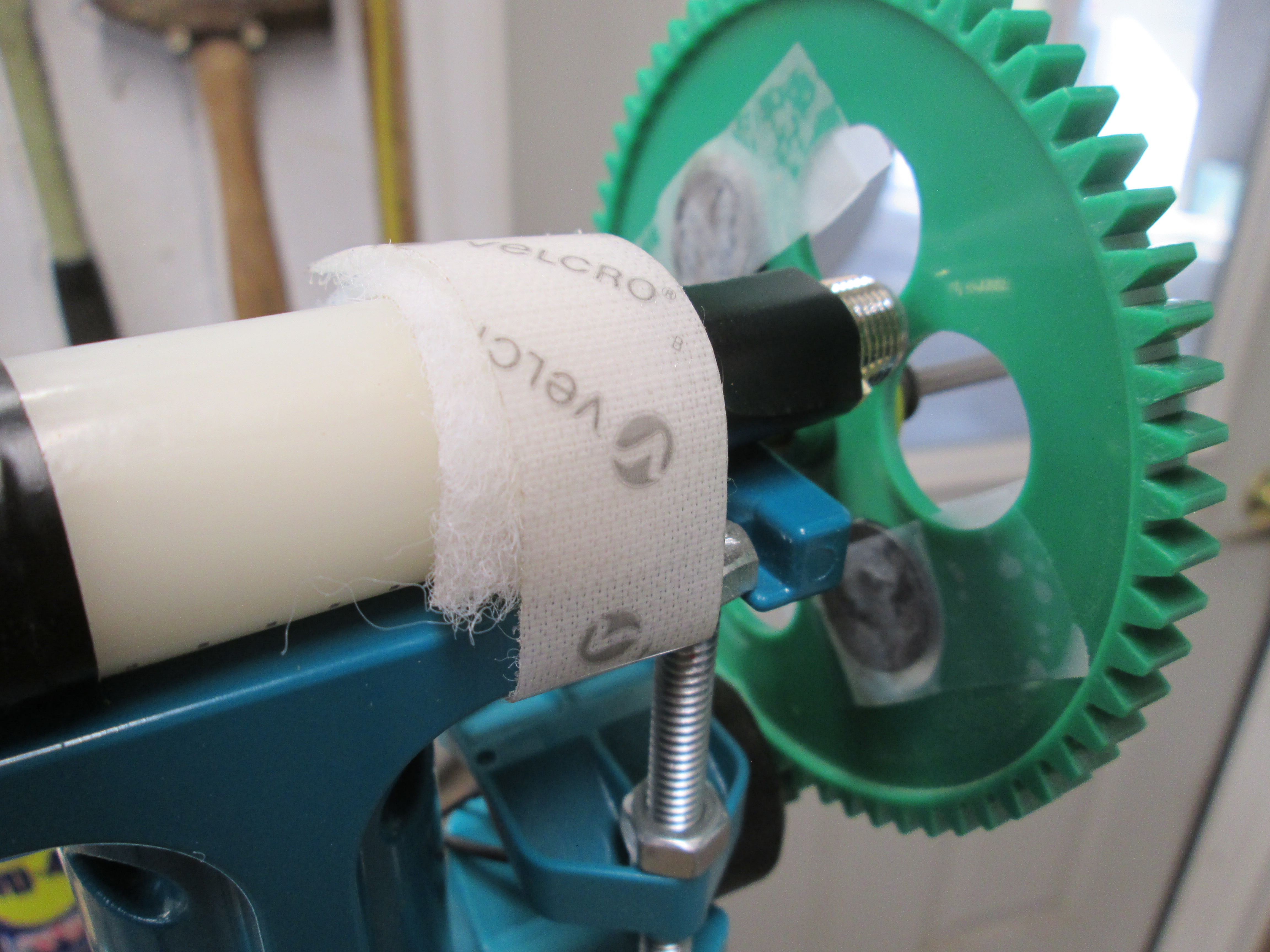
Two magnets for balance are taped opposite polarity into the holes in the KidWind 64 tooth gear. The sensor is held in position with velcro tape.
Cable management has been improved by taking Aaron Johnson's idea. The cables used to connect to the turbine being tested are attached to a board as shown. This leaves only the two alligator clips to be placed on the generator leads loose in the tunnel. The Go Direct collection unit is now out of the tunnel and out of the way. No chance of wires being caught by a rotor blade.
The other two ends are routed through holes drilled into the test chamber and then go to the Go Direct collection unit. The other green wire in this case is the connection for the RPM sensor if used,
The LabQuest and Go Direct units have been placed on a piece of foam core with fitted pockets and the whole thing sits above the fan control box. This will do well for the standard KidWind generator testing using the LabQuest unit limited to 1 amp and 30 volts.
To get around the voltage and amperage limitations for $5 I bought a 0-100 volt meter and 0-10 amp ammeter unit. It needs a power supply and I was able to recycle one from an old 12 volt wireless phone. It is note worthy that during this test when the load resistance was lowered the torque on the generator could be felt increasing. This piece of the puzzle needs more looking into and measured.
OK so now this is getting a bit more complex. On the left is a 25 watt 0 to 100 ohm rheostat for loading the generator. A calculator for figuring out the wattage produced by the generator. The 0-100 volt and 0-10 amp meter display. And last the RPM led display. This would take care of the physical display for all the data collection devises.
After a few You Tube video's and some head scratching it was time to draw out the wiring schematic. Each unit (volt/amp meter and RPM sensor) would get its 12 volt operating power from the recycled phone transformer. The 0-100 ohm rheostat would be wired in series with the ammeter.
OK so here is the physical wiring of the components. Doing this gives one more appreciation for the work done by Tuescher Electric on the Control box for sure.
And here is the new data collection system and a test run of some data collected with it.


No comments:
Post a Comment